AI Compute Containers
Pre-engineered modular pods deployed in phased blocks as tenant demand materializes.
Up to 80 kW/rack
Infrastructure Platform
An institutional-grade compute and energy platform built on contracted utility capacity and deployed in modular phases against tenant demand — not against speculative interconnection timelines.
Deployment Architecture
Each campus layer is engineered to commission in parallel with the layers above and below it — substations land while compute pods are being staged, fiber arrives ahead of network turn-up, and operations come online before tenants energize.
This is what compresses speed-to-revenue: a stack architected for concurrent deployment rather than the sequential dependencies of traditional hyperscale construction.
Building Blocks
Pre-engineered modular pods deployed in phased blocks as tenant demand materializes.
Up to 80 kW/rack
Medium-voltage distribution architected for phased build-out toward the portfolio's 180 MW ceiling.
Sized per phase against contracted tenant load.
On-site BESS for load balancing, peak management, and optional grid-response service revenue.
Sized for tenant load-balancing and peak-management requirements.
Air- and liquid-cooled options sized for high-density GPU clusters across multiple workload profiles.
Air + Liquid
Diverse-path fiber routing engineered for tenant-grade redundancy and inter-campus connectivity.
Diverse-path fiber routing engineered for tenant-grade redundancy.
24/7 network operations center, security monitoring, and tenant support functions on-site from Phase I.
24/7 · On-site
Speed to Power
Build Pipeline
Phase I
Active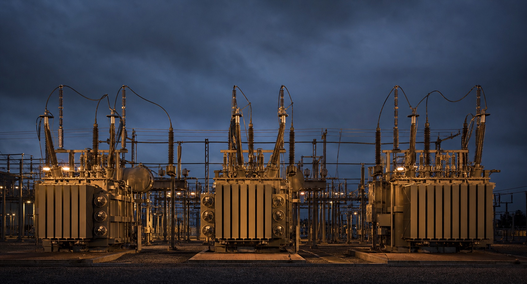
Phase II
Planned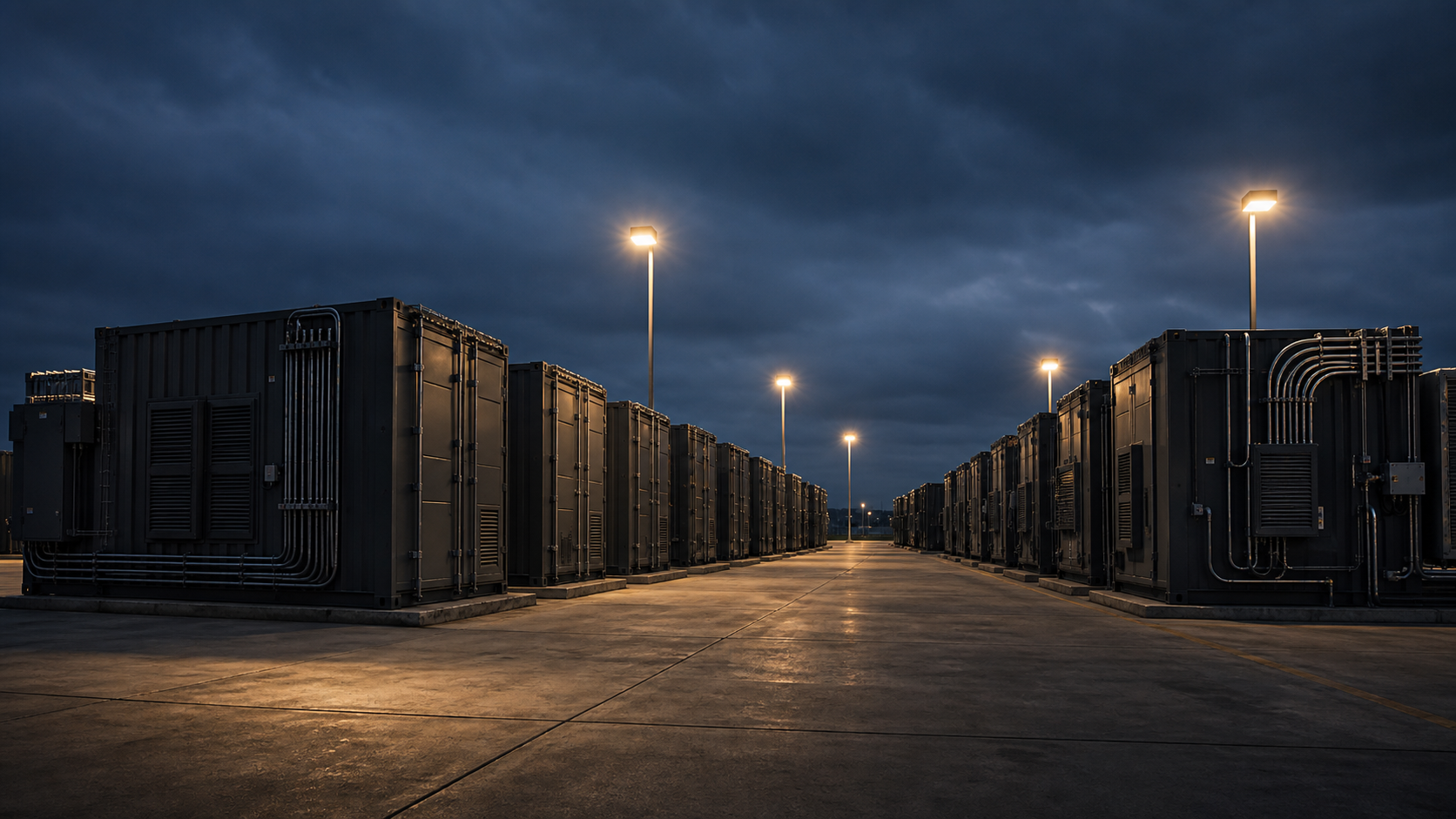
Phase III
Future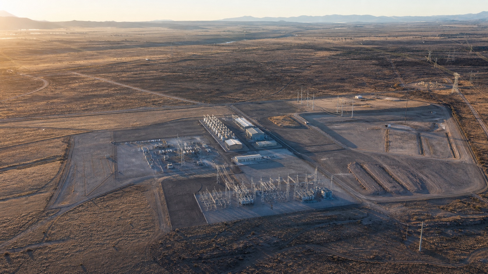
Dig Deeper